

Two paper-based packages can have nearly identical finished dimensions yet consume substantially different amounts of material. The difference is not necessarily caused by board thickness, decorative finishes, or the complexity of their appearance. It often originates in the relationship between structural geometry and the manufacturing process used to convert flat sheets into finished packaging.
A package must first be translated into a manufacturable dieline. That dieline must then fit within a production sheet while satisfying material orientation, printing, die-cutting, and assembly requirements. Each restriction can reduce the number of usable components obtained from a sheet.
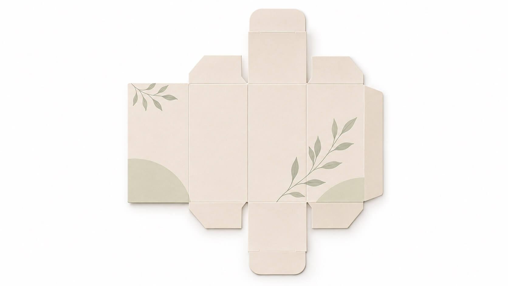
For packaging buyers, the relevant question is therefore not simply how much material a finished box contains, but how much material must enter production to obtain one acceptable box.
Understanding material specifications, structural development, and production validation helps explain why seemingly similar designs can produce different quotations. More importantly, it reveals which losses can be reduced through engineering and which are necessary to maintain manufacturing reliability.
Why Does the Same Finished Box Size Require Different Amounts of Material?
Finished dimensions describe the space occupied by a package, but they do not describe its material requirements.
A packaging structure consists of functional panels, closure flaps, glue tabs, overlapping sections, and sometimes additional components. These features form its developed blank, which may occupy considerably more material than the visible exterior surfaces suggest.
Consider two structures designed around products of similar dimensions. One uses a conventional rectangular construction with a compact arrangement of panels. The other requires extended closure flaps and angled connecting sections.
Even before nesting begins, the second structure may contain a larger retained blank area.
This distinction is especially relevant to custom pyramid boxes, where triangular panels and closure geometry influence both the amount of material retained in each blank and the spaces left between neighboring blanks.
However, an irregular outline does not automatically mean poor material efficiency. Certain custom shape boxes can be arranged in alternating orientations so that projecting sections occupy otherwise unused spaces.
A manufacturer must therefore evaluate two separate variables: the actual area of each developed component and the number of components that can be produced from the available sheet.
Confusing these variables can lead to incorrect conclusions about which design is more economical.
How Should Sheet Utilization Be Measured?
The first useful measurement is geometric material utilization.
For a structure produced from one type of sheet material:
Geometric utilization (%) = Total retained component area ÷ Total input sheet area × 100
Retained component area includes all material remaining in the finished packaging component, including necessary flaps and glue tabs. It excludes offcuts, removed windows, and other discarded regions.
Suppose two layouts use identical 700 × 1,000 mm sheets. Each packaging blank has a retained area of 100,000 mm².
|
Parameter |
Layout A |
Layout B |
|---|---|---|
|
Input sheet area |
700,000 mm² |
700,000 mm² |
|
Retained area per blank |
100,000 mm² |
100,000 mm² |
|
Blanks per sheet |
5 |
4 |
|
Geometric utilization |
71.4% |
57.1% |
|
Geometric offcut proportion |
28.6% |
42.9% |
Illustrative calculations only; not factory production data.
Layout A produces more components from the same material input. Yet this calculation does not establish which layout will deliver the lowest cost per acceptable package.
It measures geometric utilization, not manufacturing yield.
That distinction becomes important once the design moves from computer-generated nesting into actual production.
Why Can a More Efficient Nesting Layout Perform Worse in Production?
A dieline cannot be rotated, compressed, or positioned solely to maximize the number of blanks per sheet.
Paperboard is an anisotropic material: its properties differ along the machine direction (MD) and cross direction (CD). The relationship between fiber orientation and critical creases influences folding behavior, dimensional stability, and the risk of visible surface defects.
The correct orientation depends on the selected board, its thickness, coating, crease geometry, and the package’s folding requirements. It should be verified through material-specific converting trials rather than determined by a universal rule.
For example, rotating a long, narrow blank by 90 degrees may improve nesting. However, the new orientation may also change how the main creases behave during folding.
This issue can arise with custom lip liner boxes and custom mascara boxes, where elongated panels appear easy to arrange in repeated rows.
Crease performance is also influenced by tooling. Creasing-rule width, channel width, penetration, and the compressibility of the paperboard must work together to produce a controlled folding hinge. An inappropriate combination can increase cracking, spring-back, or inconsistent folding.
Printing and die-cutting introduce further constraints. Production sheets require suitable gripping and registration areas, while cutting layouts must maintain enough structural integrity for transfer and waste removal.
Small connecting points, known as nicks, may temporarily hold blanks within the sheet during die-cutting. Their location and strength must balance reliable sheet transport against clean separation during stripping.
A tightly nested arrangement that causes premature separation, unstable waste removal, or frequent machine interruptions may have a higher geometric utilization but a lower practical output.
The correct engineering objective is therefore maximum usable output under validated production conditions, not maximum theoretical nesting density.
Where Does Material Waste Actually Accumulate?
Once the layout is approved, additional material consumption occurs throughout the converting process.
These losses should be classified by origin because each category requires a different corrective action.
|
Loss category |
Typical cause |
Main improvement approach |
|---|---|---|
|
Geometric offcuts |
Blank outline and sheet arrangement |
Dieline and nesting optimization |
|
Setup consumption |
Printing registration, color adjustment, machine preparation |
Process preparation and repeatability |
|
Converting rejects |
Cutting defects, crease cracking, stripping failures |
Material-tooling compatibility |
|
Finishing rejects |
Surface damage, wrapping defects, misregistration |
Process control and inspection |
|
Assembly rejects |
Poor fit, adhesive defects, component misalignment |
Assembly validation and component control |
For luxury cosmetic packaging, the calculation becomes more complex when the structure combines printed board, decorative covering paper, and separately manufactured inserts.
A defect in the covering material may cause rejection even when the structural board remains acceptable.
Likewise, custom jewelry packaging frequently requires several components with different manufacturing routes. The outer structure, decorative lining, and product support may each have a separate material yield.
For custom jewelry packaging boxes, combining these components into one unexplained waste percentage can conceal the actual source of excessive consumption.
Another important distinction is the stage at which a defect is discovered.
A rejected sheet identified immediately after printing has not accumulated the same conversion and assembly costs as a nearly completed package rejected during final inspection.
Material losses should therefore be recorded by operation, while cost losses should account for the value added before rejection.
This creates a more useful basis for production improvement than a single overall scrap figure.
Why Is Material Utilization Different from Manufacturing Yield?
Geometric utilization describes how much of a sheet becomes packaging components.
Manufacturing yield describes how many components or packages satisfy the required quality specification.
They are related, but they measure different outcomes.
A layout with low offcut waste may still produce a high number of rejects if its cutting or folding conditions are unstable.
For a simplified single-component package, expected material consumption can be estimated as:
Required sheets = Target acceptable quantity ÷ (Blanks per sheet × Expected acceptance rate)
This relationship assumes that the acceptance rate represents the complete relevant production process and excludes separately calculated setup consumption.
Consider an illustrative order requiring 10,000 acceptable packages:
|
Parameter |
Layout A |
Layout B |
|---|---|---|
|
Blanks per sheet |
5 |
4 |
|
Expected acceptance rate |
92% |
99% |
|
Sheets required, before setup allowance |
2,174 |
2,526 |
|
Expected acceptable packages |
≥10,000 |
≥10,000 |
Sheet requirements are rounded upward. Acceptance rates are hypothetical and are not presented as industry benchmarks.
Despite its lower acceptance rate, Layout A still consumes fewer sheets in this example.
This matters because a higher rejection rate does not automatically eliminate the benefit of better nesting. The result depends on the actual values.
For custom printed lotion boxes, manufacturers may need to compare alternative orientations or layouts when printed graphics, coatings, and crease requirements affect both sheet yield and rejection risk.
The same calculation applies to diffuser boxes wholesale projects, although protective inserts and other independently manufactured components must be assessed separately.
The next question is whether the lower material input also produces a lower total manufacturing cost.
When Does Lower Material Consumption Fail to Reduce Unit Cost?
Material cost is only one component of manufacturing cost.
A more complete comparison includes raw material input, printing and converting operations, setup consumption, tooling, assembly labor, quality losses, and any additional handling required by the selected design.
A simplified comparison can be expressed as:
Cost per acceptable package = Total attributable manufacturing cost ÷ Number of acceptable packages
Suppose Layout A saves material but requires slower stripping, more manual separation, or additional inspection.
Its material cost may be lower while its converting cost is higher.
Conversely, a layout with more offcuts may support stable machine operation and reduce labor or downtime.
This is why a manufacturer should not automatically select the arrangement with the highest nesting percentage.
For a meaningful comparison, both alternatives must be evaluated using the same product specification, quality acceptance criteria, and cost boundaries.
Material prices, machine rates, tooling assumptions, and production quantities must also be stated consistently.
Only then can a buyer distinguish a genuine engineering improvement from a reduction in one cost category that simply shifts expense elsewhere.
Can Different Packaging Components Be Combined on One Sheet?
Mixed-component nesting can improve utilization when different outlines complement one another.
However, shared production requires more than matching available space.
Components must be compatible in substrate grade, caliper, grain direction, printing requirements, finishing sequence, and production timing.
Different artwork may require separate printing arrangements even when the board specification is identical. Unequal order quantities can also create surplus components when several products share a fixed production ratio.
For international jewelry packaging, variations in product assortments, regional information, or presentation requirements may further restrict shared-sheet production.
The economic decision should compare material savings against additional setup, sorting, identification, inventory, and production-control requirements.
Mixed nesting is valuable only when it improves the overall manufacturing result.
What Technical Evidence Should Buyers Request Before Approving a Structure?
When comparing jewelry packaging manufacturers, cosmetic packaging suppliers, or a luxury packaging manufacturer, buyers should request evidence that explains material consumption rather than accepting an unsupported waste percentage.
A technically useful quotation should identify the material grade and thickness, production sheet dimensions, retained component area, number of blanks per sheet, and required grain orientation.
For multi-component structures, the calculation should distinguish outer packaging, covering materials, inserts, and other separately converted parts.
Where material efficiency is commercially significant, the manufacturer should also explain the assumed setup allowance, expected production acceptance rate, and any constraints that prevent a more compact layout.
Before approving tooling, brands can request a comparison of alternative dielines or sheet arrangements. The alternatives should then be validated for crease performance, cutting quality, stripping stability, assembly fit, and finished appearance.
This process provides a defensible answer to the central question.
Different packaging structures produce different material waste rates because their geometry, material orientation, tooling requirements, and manufacturing stability interact.
The most economical design is not necessarily the one with the smallest blank or the least offcut area. It is the structure that achieves the required quality with the lowest justified total cost per acceptable package.